We’re gearing up for an incredible 6,000+ tonne project running from 2026 to end of 2027 — and it’s a beauty! With 55 cross tunnel passages spaced every 100 metres, that means 110 cross tunnel openings across the twin tunnels. Each of those openings is made up of 6 segments, each weighing around 10 tonnes — that’s a whopping 660 segments in total!
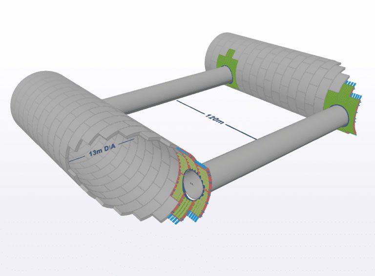
Example of Main Tunnels showing cross tunnel passages with openings.
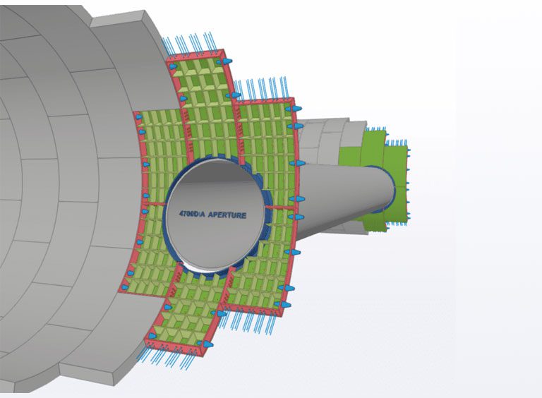
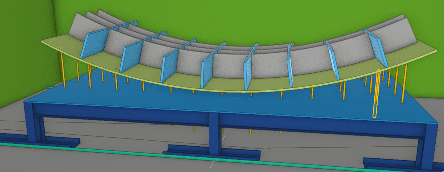
Example of Tunnel Opening, made up of 6x segments
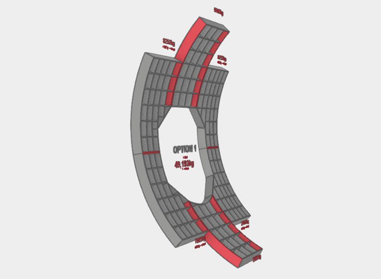
Example of Segment – approx 10 tonne
The manufacture of the steel tunnel segments at the location of the cross passages are an important part of the tunnel project. For the installation to go well, the accuracy, quality and volume of the segments need to be aligned to the Tunnel Borning Machine (TBM) progress with appropriate contingent to account for any variances in progress (if TBM is ahead of schedule) or to accommodate for any delays in manufacture for whatever reason and so as to avoid any chance of delaying the tunnel boring progress.
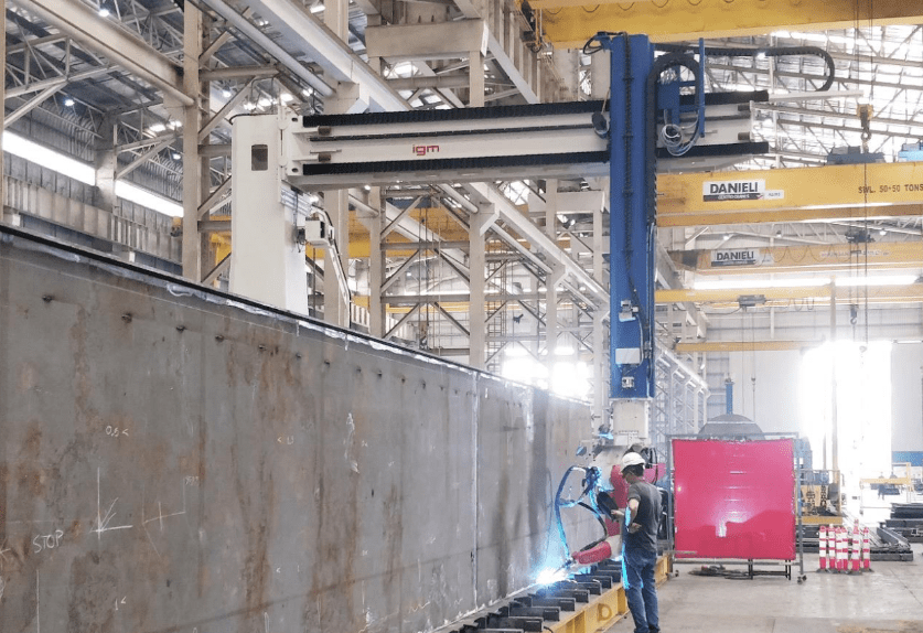
Delivery of the pre-processed elements to Bowhill’s site via standard gauge semitrailers. These items will come cut to shape, ID numbers etched onto the components (traceability assurance) bevel prep as required, holes drilled, tapped, and rolled to shape as required. Plates are processed on their state of the art CNC plate profiling equipment which includes a significant multi spindle drill/mill head incorporated into the gantry of the machine as per photo above.
Example of what the component pack would look like on timber bearers awaiting loading into fabrication jig.
Checking and sorting into “component packs” for the fabrication team to load into the assembly jigs. Loading of jigs will take place under the hook of the B5 main fabrication facility which will be serviced with 3 overhead cranes with a capacity exceeding 30 tonnes each.
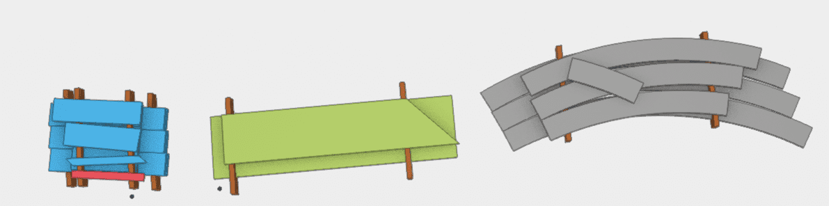
Fabrication of components on a series of special purpose fabrication jigs that also act as error-proofing gauges and are adjustable to allow fine tuning to tolerance during the initial stages of manufacture. (Bowhill propose to involve a specialist repetition manufacturing consultant to assist with the design of suitable process flow and inclusive of fabrication jigs, cycle times analysis etc. The initial thinking of Bowhill management is investigate the develop something similar to the below picture. This approach is inspired by technology called “adaptive mould”, Bowhill would propose that this be adjustable manually rather than electronically (threaded rod for example as demonstrated in yellow) for this style of work, given that the radius is identical for the entire project.
Broad concept for fabrication jig, TBC.
Manufacture up to machining stage to occur in Bowhill’s new B5 high bay, heavy lift workshop
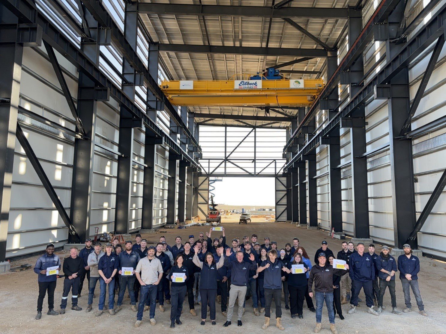
Photo above shows only the 100t crane, there are 2 more 30t cranes to be installed on the lower-level runway beams all of these cranes can service the entire floor area of the building. Building is 70m long, 23m wide and 23m tall.
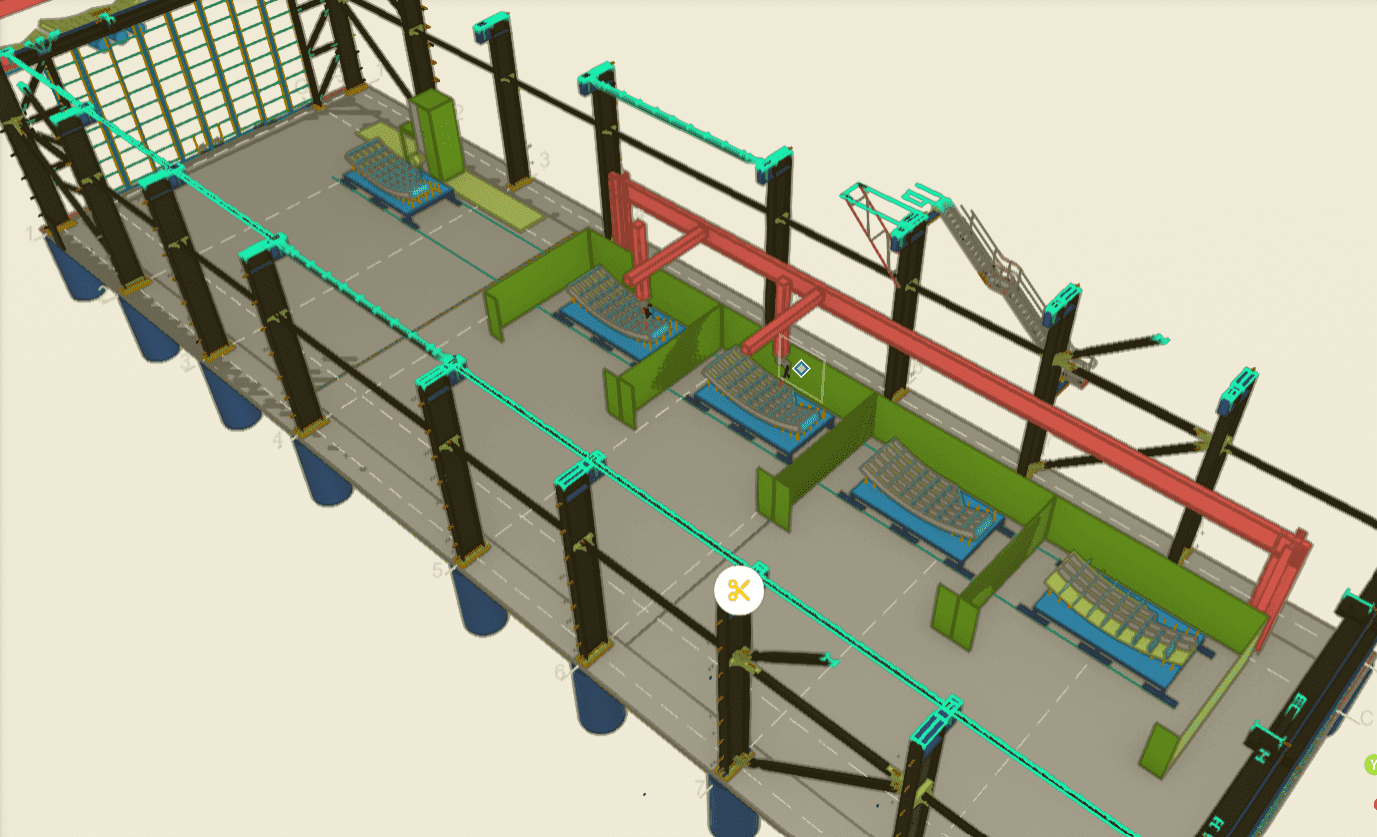
Plan is to dedicate the entire western side for the fabrication and welding of the T2D tunnel segments as shown on the below layout.
Tacking of components to a level that will hold whilst undergoing the welding process is to be done as part of the fabrication process. Strategic tack locations to avoid compromising the weld strength.
Welding is to be conducted by traveling robotic units that will relocate to the segment in its fabricated location. This will happen safely inside a welding cell that will be designed in alignment to the current Australian safety Standards complete with solid barriers (weld flash) and electronic interlocks to ensure no physical danger to humans in the vicinity of the robotic operation. Welders are equipped with scanning heads to ensure that the weld placement is true to the unique physical components of every weld, not just to the electronic model’s theoretical measurements of where the welds should be.
Example of similar size robotic machine layout – provided by IGM
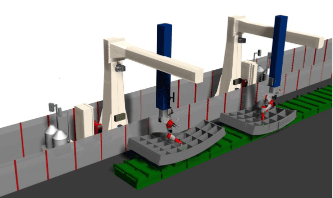
Electronic mockup of robotic welding stations welding tunnel segments – provided by IGM
Example of similar size robotic machine layout – provided by IGM
Inspection post welding by qualified NDT technicians to ensure weld integrity and compliance, QA to use physical ID (etched onto steel plate at processing stage) data capture at every step in the manufacture process using handheld tablets for live, up to date data.
Segment movement via forklift to the machining station (separate building) where a suitable CNC horizontal boring machine will skim slightly oversize segments to square/true, within tolerance on the connecting faces. Aiming for removal of less than 2mm of material on each face. Gasket grooves are machined once the connection face is “cleaned up” to the size and profile as specified by T2DA.

Initial segment sets to be bolted together and measured/scanned to ensure conformance to tolerance, once this process is proven over the course of the first few sets Bowhill propose to reduce the frequency of full assembly and measurement to the satisfaction of the T2DA superintendent. Segments would be bolted together in their full set as per model snap below.
scope of mock assembly for measurement purposes
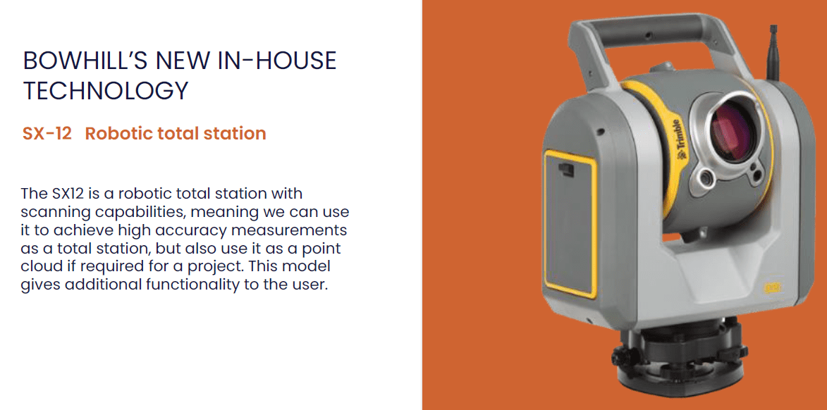
Electronic dimensional check via robotic total station
Transport to site can be coordinated to support the tunnel lining team, and to replenish minimum stock levels, suggest appropriate stock to be held on hand at both T2D site and at Bowhill to reduce risk of delays caused by waiting for steel lining segments.
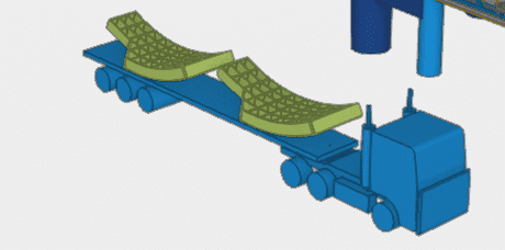
Concept transportation of segment pieces


